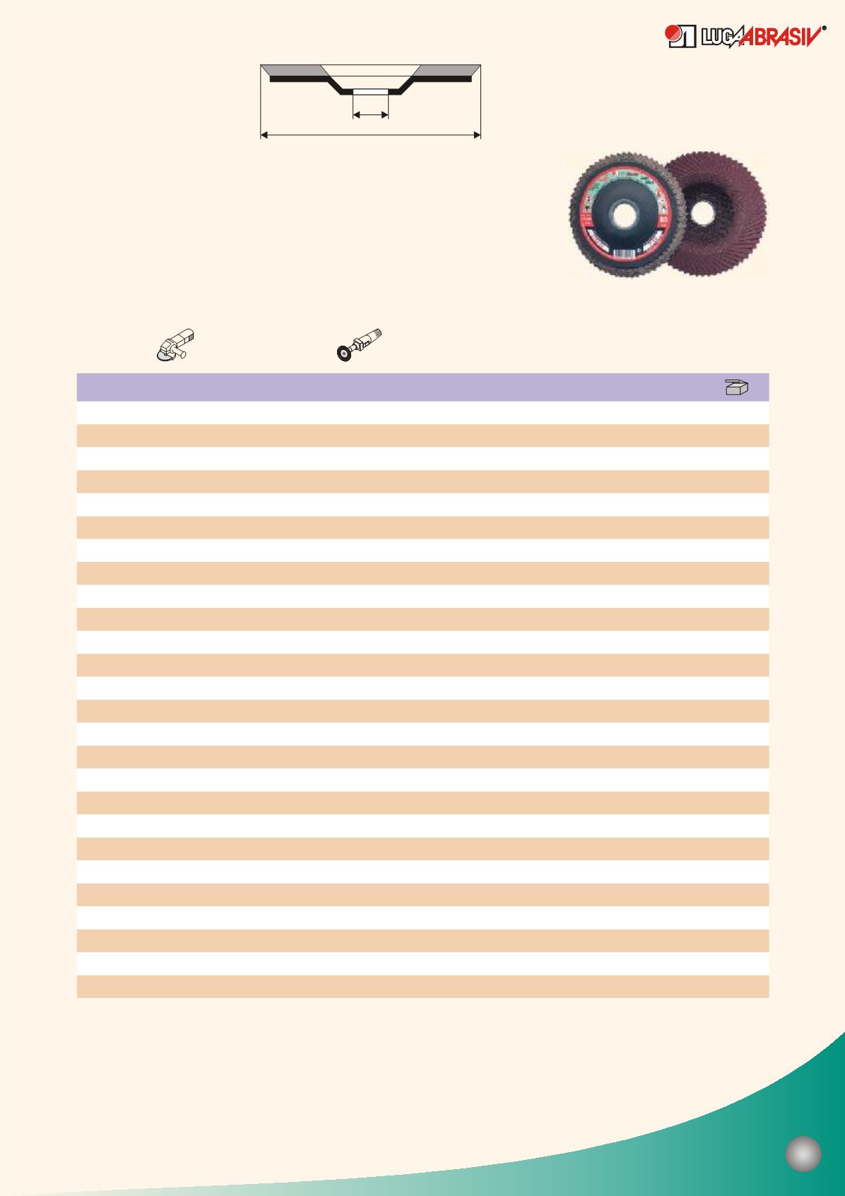

D
H
125
125
125
125
125
125
125
125
125
125
125
125
125
115
115
115
115
115
115
115
115
115
115
115
115
115
22.23
22.23
22.23
22.23
22.23
22.23
22.23
22.23
22.23
22.23
22.23
22.23
22.23
22.23
22.23
22.23
22.23
22.23
22.23
22.23
22.23
22.23
22.23
22.23
22.23
22.23
80
80
80
80
80
80
80
80
80
80
80
80
80
80
80
80
80
80
80
80
80
80
80
80
80
80
13300
13300
13300
13300
13300
13300
13300
13300
13300
13300
13300
13300
13300
12250
12250
12250
12250
12250
12250
12250
12250
12250
12250
12250
12250
12250
The plant receives the orders of wheels manufacturing with dimensions and characteristics
not indicated in the given table.
А 24
А 24
A 36
A 36
A 40
A 40
A 50
A 50
A 60
A 60
A 80
A 80
A 100
A 100
A 120
A 120
A 150
A 150
A 180
A 180
A 240
A 240
A 220
A 220
A 320
A 320
208
D,
mm
H,
mm
Type KLT 4
The new flap disposing structure increases the wheel
flexibility and thus gives an opportunity to treat contour
surfaces of the details and constructions made of different
types of steels, non-ferrous metals and wood.
Contact zone between working area of the wheel and
the product is 40% more than that of KLT 1 and KLT 2.
Using KLT 4 you can achieve high-quality treatment
quicker than with the fiber disc.
80m/s
Working speed,
RPM
Characteristic


